Virtual LIDAR – Proof of Concept

As you may have seen in my previous post on The Luggage I’ve been hard at work rebuilding it anew and adding new features. I mentioned I wanted to have basic control as soon as I switch it on, this had to include safety features to prevent it running in to obstacles, either stationary objects or people. I don’t want it to gain it’s namesakes reputation after all.

In this post I’ll explain how I fused data from four LIDAR scanners with the aim to simplify usage in obstacle avoidance and increase safety of the robot.

The Luggage, v2

Since the inception of this project the cost of LIDAR scanners has dropped to an almost laughably low price, so seemed rude not to take advantage of this. Enter, the OKDo LIDAR, which even at £50 is pretty cheap, however if you look on eBay you can find them for £12 each. I linked to RS as it’s a page less likely to disappear than a random eBay auction.

These scanners are cheap enough I bought one for each side of The Luggage, I figured they would make excellent safety curtains as in basic mode I could just program the motor controllers to enable the brakes if anyone or thing got too close.

For those not familiar with LIDAR scanners they are simple in concept, they have a spinning laser range finder and they output data for 360 degrees over serial. This is a 2d LIDAR as it provides distances on a plane around itself, imagine a RADAR screen from pretty much any movie or show you can think of and it’s the same concept. You can get 3d LIDAR scanners however they are eye-wateringly expensive.

Output from these is essentially key/value pairs of angle and distance, you get luminosity data for each point too which tells you how strong a signal it was based on. You can use this for simple filtering as a strong return could have higher confidence than a weak one for example.

As I want to have a basic operating system for this robot running on microcontrollers I thought about how I may be able to simplify the setup to reduce the processing cost on the motor controller. With four LIDAR scanners outputting at around 250kBps that has the possibility of swamping an MCU with data, so I thought I’d dedicate one to the task.

Four LIDAR scanners taped to a cardboard box, cardboard-aided-design at it’s finest!

I created a simple rig using a cardboard box to mount four of the scanners with an object between them to simulate the body of the robot. I connected the outputs of each to the hardware serial inputs on a Teensy 4.1 and wrote some code to transform the polar coordinates provided by the scanner in to cartesian coordinates relative to the centre point of the box.

Data visualised in Unity using four colours, one for each LIDAR scanner

This fused dataset is then output over USB serial to the host, but importantly can also be output to one of the other hardware serial ports to be used by another microcontroller. In the image, above, you can see the data visualised in a simple Unity application I threw together for debugging.

The result of this is that I can output a stream of data with (x,y) coordinates, this allows another microcontroller the much easier task of “if object less than X or Y distance, stop” rather than having to calculate this itself from the raw data.

In the image above you can see solid lines in multiple colours showing how the same objects were detected by a few of the scanners, they don’t perfectly overlap but it was good enough to prove the concept as it mapped nicely to the layout of my living room. It did suffer from some strange circular artifacts around the centre which pulsed in and out, this is a problem for Future Keegan, he loves things like that…

Going back to the concept of simple behaviours on power-up and extending with compute, the Teensy also has the option to output raw data on a second virtual USB serial port. This would allow me to utilise the raw data from the sensors with existing tools and packages, in ROS for example, as a simple node would be able to split the four raw streams in to separate ROS topics.

If you want more detail on how I implemented this, baring in mind it is only a proof of concept and shouldn’t be considered functional, feel free to have a look at the code here.

The Luggage, a Recap

A long overdue update on The Luggage, a long running project to build a cargo robot that can follow me around and double as transport at events.

Since EMF 2016 I’ve had the idea for a project I’ve apparently only mentioned in passing on here, The Luggage. Borne of the frustration of lugging camping gear from carpark to campsite, I joked that ideally I’d have something like the “half suitcase, half homicidal maniac” better known as The Luggage, but with less of the mania…

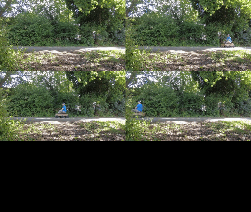
Me riding the prototype Luggage

Ultimately it’s morphed in to a cargo robot that has enough payload capacity to carry 100KG+ that can follow me around. It should also serve double duty as a ridable vehicle to get around the various events I attend.

Through a few false starts, including an attempt to make a Hacky Racer with legs, I ended up with a six wheeled prototype that worked for a while and proved the concept at least. It used six recycled off-road hoverboard wheels, three ODrive motor controllers, and a Raspberry Pi to coordinate them all. As you can see from the GIF above, it could carry me no problem, not a surprise as I already knew four hoverboard motors were plenty to craft an excellent Hacky Racer. As a real world test I managed to move around 750kg of 1000kg’s worth of flooring compound up our garden to the workshop. I stopped for lunch when the bot decided to stop itself and put it on charge while I grabbed lunch.

What I thought was a flat battery turned out to be a dead BMS.

The Luggage prototype shortly before self destruction…

It turns out what I thought was a 90A BMS was only rated for 60A, as each of these motors are rated at 10A with a higher stall current setting off uphill with low battery was enough to push the BMS passed it’s limit. I’m not sure how as this is exactly the sort of thing it was designed to prevent, it should have cut out at 60A, or whatever its peak current is.

Lessons Learned

As well as the obvious issue with the BMS dying there were a few other things I learned along the way I took with me in developing the next version, mostly though it was the control system.

In the prototype I was using ODrive motor controllers, the v3.6 56v models, and I bought genuine models after seeing James Bruton use them with great success in various projects. They even have a guide on using them with hoverboard motors which seemed ideal! It turned out that though they could work with them in theory, they left a lot to be desired in practice. ODrive’s were originally designed to enable precise control of brushless motors for robotics, this included using encoders to accurately measure the movement of the motors to enable that control. Encoders typically give upwards of 4000 ticks of measurement per revolution, the hoverboard had hall effect sensors which gave only 90.

I got them working, as you can see above, but the motors juddered and oscillated a lot which stationary which wasn’t ideal. They also have excellent stall and overcurrent prevention, sadly this constantly triggered and motors would error out and stop working all the time, putting extra load on the others. They were also expensive if you bought the genuine articles, or just generally terrible if you bought the cheap clones. I don’t want you to think I’m bashing on ODrives, they brilliant bits of kit but the wrong tool for this job.

I tried to use hacked hoverboard controllers, based on work by OG Hacky Racer Lucy Rausch, but boards were getting more difficult to come by and lower quality too. There used to be one or two models of these boards, now they’re being pumped out in a number of variations and it’s difficult to know which you’re getting until it arrives. Frustrating, unpredictable, and a waste of time and cash sadly.

Another frustration of my own making was that when The Luggage was powered on, I still needed to log in to the Pi to get everything started. This could have been solved with a startup shell script but with the motors erroring out as often as they did I never got that far.

New Beginnings

Cutting my losses, I started again and rebuilt the base from scratch. I’ve shortened the wheelbase to give better torque when skid steering on the spot, I also added independent suspension to ensure the wheels have a better chance of maintaining traction. The prototype had fixed wheels and a slightly bent frame resulting in an ungainly tripod.

The Luggage, v2

I’ve kept the six hoverboard wheels but made a new battery pack from a scavenged electric car battery module, I’ve gone a little overkill with a 250A BMS but I plan on adding a large inverter for mobile power from this too so it’ll be useful in the long run.

Another requirement I set myself was basic and safe operation immediately when powered up. I wanted to be able to switch on the robot and be able to drive it around, to unload from my car for example or just give a quick demo. To enable this I decided on using microcontrollers to interface between remote and motor controllers to essentially turn it in to a massive RC car. The idea is I’d get basic control immediately, but if I wanted more complex behaviours I could boot up a computer to add autonomy.

I also needed a cheaper and more suitable option for motor control, I did look at VESCs but they’re also pricy and a bit overkill. I’d seen a few people using the RioRand controller for this but I didn’t realise it could be easily used with a microcontroller until I saw this post by Mad EE. Basically, it has an undocumented header that can be used to control the throttle and get speed feedback too.

I’ll go in to more detail on each subsystem in their own posts, this has got a bit long as it is, but I thought I’d share a long overdue update on this project and hopefully regain some momentum.

PiWars 2024: The Challenges and Their Challenges

There are seven challenges at the in-person event for PiWars 2024, each with their own problems to solve. They are split in to three categories: Autonomous only, Autonomous/Remote, Remote Only. For the second of those, if you are in the Advanced/Professional category you have to attempt the challenge autonomously.

State of the Onion

NE-Five exists as a robot, the base hardware is all there and everything has met the minimum requirements as I’ve set them, the devil is in the detail though and integration hell is totally a thing. Also, perfect is the enemy of done and I really need to get a focus on what needs doing now vs what would be nice to have.

Motor control

Motor control has been overhauled with the switch from Red Robotics RedBoard hat to the Pimoroni Yukon. The big difference is the latter has support for encoders, but it also has on board processing which means that processing load is taken away from the overhead on the Raspberry Pi. I also have a ROS node for the Yukon so it can send and receive ROS messages such as motor velocity commands and odometry.

Servo Control

I’ve implemented a new ROS node that not only takes commands to move the robots arms but also provides joint state feedback to the wider ROS system, this also includes the neck servos as they are the same Dynamixel smart servos used in the wrists. The linear actuator that adjusts how high the robot is standing has also been hooked up to the Yukon, it has a feedback line that is factored in too. Each of the smart servos is independent of the Pi too as you give them a command and they do it, handling any PID loops and monitoring internally as needed.

Camera System

I’m still using the Luxonis FFC-3P camera system, with two wide angle global shutter cameras and a narrower field rolling shutter camera in the centre position. Luxonis have recently released a big update that includes on-device pointcloud generation. Previously I was trying to do this on the Pi and it was basically taking all the resources just to do that. Having this board run tasks itself and only providing the data the Pi needs is a big win for sure.

I’ve also been playing around with object recognition, it works and you can run custom neural networks on their which, again, means the Pi doesn’t have to do anything but use the data it produces.

Back to the Challenges…

The robot works great in remote control mode, it’s currently the only mode however which isn’t ideal. There are five challenges I’ll have to tackle autonomously so I’ll concentrate on those for now.

Lava Palava

This is a line following drag race, there is a course with a black floor and white strip down the middle which the robot has to follow as quickly as possible. The course has a chicane in it from previous years but this year will also have a speedhump.

With the motor encoders providing feedback with regards to distance travelled and the camera system able to detect objects, I intend to combine the two to have it aim for a goal that’s X meters in front of the robot and have it follow the line until it’s travelled that far. Or until I push the estop button if it tries to run away…

Eco-Disaster

In this challenge you have to sort a number of red and green barrels in to blue or yellow areas of the arena. Starting in one corner of the arena, NE-Five should be tall enough to be able to detect all the objects it needs to look out for, the start position and two sorting zones are also known locations which helps. Using a similar setup to Lava Palava I should be able to use the detected barrels to position the robot relative to them so it can pick them up. Using odometry and being able to see the coloured sorting zones, it should be able to navigate to them to drop them as needed.

Escape Route

This challenge has to be run without the robot’s operator being able to see the arena directly. For remote control this means using cameras or have someone shouting out commands, for autonomous the operator needs to be behind a screen still but only press “go” and hope for the best.

The arena will be in a randomly selected configuration out of six possible layouts. There are three coloured blocks, each having known dimensions. The plan is that as soon as the challenge begins, the robot scans to see which block is closest and add a waypoint to get passed it. After it gets there, or while en route, it can look for the next block and figure out its next steps there too.

Similar to Lava Palava, where it’s aiming for a point a certain distance ahead, the end goal will be passed the yellow line with intermediate steps to get around each block. The depth camera already has an option to convert a depth image to laser scan so should be relatively easy to detect a clear path.

Minesweeper

For this one, the robot will have to look for an illuminated red square and move to it. Once it has visited that square another will light up, the process repeats. As with Escape Route and Lava Palava I’ll be looking for the specific colour of the square but this time I’ll be setting it as the waypoint to move towards. Once it detects it’s on top of a red square, it’ll stop. Once the red switches off it’ll start looking around for anything of the same colour, with the wide angle stereo cameras this should give a good field of view for this and the odometry once again comes in to play.

Zombie Apocalypse

This one is currently the biggest unknown as I don’t have a projectile launcher for the robot yet, I do have a pile of parts however… Sample designs for the zombie targets have been released though, so I’m planning on trying to detect those to use for the coordinates. I have parts from an electrically fired Nerf gun so will mount that on a pair of servos for pan/tilt and use them to aim at the target. I also have a green laser for this, so hopefully will be able to detect when the laser is within an area in the centre of the target before firing.

If’s, But’s, And Maybe’s…

Other than for the last challenge, I pretty much have everything in place. The devil’s in the details with these things but I’m in a considerably better position than any previous competition which is a great feeling. What are the priorities though?

The Toad List

What needs doing?

  • Nerf gun and mounting hardware
  • Camera to provide coordinates of:
    • A white line, it’ll have length rather than being point data so probably just “make sure white line is in the middle of the view”
    • A zombie, there will be multiple at different heights, the higher ones having more points available. Primarily we’ll need the X,Y coordinates but detecting distance will help ensure were detecting the right things as they’ll all be on a plane.
    • Coloured boxes, these will be used as signposts and will need to be avoided. Depth to laserscan for obstacle detection.
    • Coloured barrels to pick up and navigate around, this will need pose estimation.
    • Coloured flooring, for both mine sweeper and Eco Disaster
  • Arm control to ensure coordinates are in the same system as the camera, this is for picking up the barrels
  • Waypoint system, hook in to odometry to have the robot follow a path.
  • Robot pose estimation, where is the robot and which way is it pointing?

There is a common theme in that a lot of the challenges have overlapping needs but there’s a lot of work to do.

Load’s of time though, right?

NE-Five Upgraded? Yukon Bet On It!

Upgrades galore in this latest post! Raspberry Pi 5, Pimoroni Yukon, and a banging sound system?!

I’ve been hard at work with a few upgrades on the robot over the past few months and thought I’d share a long overdue update, and if you’re here from the Raspberry Pi blog, welcome! In this post I’ll talk about some of the upgrades to the robot I’ve not covered yet, and will cover each in more detail in future posts. This includes motor control using PID loops, odometry from the encoders, and using running a ROS node on a Raspberry Pi Pico/RP2040 based board.

The key upgrades? A Raspberry Pi 5, Pimoroni Yukon, a banging sound system! Wait, soundsystem?!

Raspberry Pi 5

The Raspberry Pi 4 was a massive upgrade from the model 3, the extra RAM being the biggest winner for me, but the CPU was still a bit slow compared to some other single board computers on the market. When the Raspberry Pi 5 was announced it sounded like it was the upgrade I needed! I managed to get on the waiting list only a few hours after the announcement and a month or so later the board arrived.

Plenty of others have covered the Pi5 in more detail so I’ll not give a review here, needless to say though it’s made on-robot development *much* easier. I was running VS Code on the robot before which allowed me to develop on it remotely, this worked but had a big overhead that can swamp the Pi’s CPU and RAM if you don’t keep an eye on it. The extra power of the Raspberry Pi 5 makes the experience more responsive and makes it feel like I’m coding directly on my desktop. I’ve not scratched the surface of what it can do yet, but I’m getting closer!

Pimoroni Yukon

One of the primary issues to deal with in robotics is controlling motors, interfacing with sensors, and all the other things required to interact with the real world. Typically you have a computer of some kind coordinating all the components of a robot along with dedicated systems that handle the actual hardware involved. Think of a robot as if it’s a ship, you have the captain in overall control but they delegate specific tasks to others who only interrupt them when something needs attention. They’ll tell the engine room what speed to go at, and they’ll deal with it unless there’s a problem with the engines. They may also have a lookout who’s job it is to watch radar, sonar, or other sensors, and only tell the captain when something will cause a problem.

In this instance, the Raspberry Pi 5 is the captain, the Luxonis FFC-3P is the lookout, each servo in the arms and head look after themselves, but the motors were still controlled by the Pi. The Yukon has helped fix this by taking up the role of the engineers. It has a Raspberry Pi RP2040 chip on board, same as the Pi Pico, and modules that allow for control of specific bits of hardware. In my case, a quad servo direct module, an LED strip module, four big motor modules. Code runs on the Yukon that listens for commands from the Raspberry Pi and actions them, it gives feedback to the code running on the Pi but does the heavy lifting itself. This means I can improve speed control of the motors using encoder feedback, and also use that feedback to provide position data so the robot knows how far it’s moved from its starting position.

Banging Soundsystem

I’ve wanted to have microphones and speakers on the robot since day one, for voice interaction and teleoperation purposes, but also fun. When I saw Eagle Prime throw its first punch at MakerFaire Bay Area years ago, they had some issues to work through with the code so used its PA to blast out some tunes to keep themselves and the crowd occupied while they got thing fixed.

I ended up going with a HifiBerry Miniamp and pair of Tectonic speakers for this, Matt Perks (of DIY Perks fame) recommends them and that’s good enough for me. I also have the Raspotify service installed on the robot so I’m able to use it as a Spotify speaker, works a treat!

Mostly though, it’s the easter eggs I can add…

I’ll be going through each of the above in more detail in future posts, so stay tuned for updates!

NE-Five Visits The Touring Toolshed!

NE-Five meets the legends that are Sir David Jason and Jay Blades MBE on The Touring Toolshed!

NE-Five met the legends that are Sir David Jason and Jay Blades MBE! I was asked to go on their new tv show, now airing in the UK and available on iPlayer, to show off my long running passion project, NE-Five!

David and Jay having a laugh with NE-Five, Keegan was probably involved somewhere…
[Copyright BBC Two and Hungry Jay Media]

This was all filmed in mid 2023 and I’ve been very busy since then, so over the next week in the lead up to the episode airing on BBC Two I’ll be releasing a load of videos and blog posts showing what NE-Five can do now! I’m going to bite the bullet and finally release the CAD models too, perfect is the enemy of done and they’ll never be done!

Me and Sir David Jason, he has given me and the nation countless laughs over the years so it was amazing to return the favour with a joke or two of my own!

Stay tuned for more, and if you’re eager (and in the UK) you can check out the episode on iPlayer already! Don’t forget to check out the rest of the episodes and awesome makers that have been showcased too!

To dispel any doubts, I was featured on The Touring Toolshed showing off NE-Five as a personal passion project and not on behalf of Neave Engineering, this doesn’t imply endorsement by the BBC or Hungry Jay Media. The BBC is an amazing institution and needs protecting, just ask Public Service Broadcasting!

NE-Five Mk4 – It’s All About That Base…

An update on the design of NE-Five Mk4

The road to PiWars continues! Most important of all is a solid base to build from so that’s where we’re starting.

A render of the new design for the robot base. It has a mecanum wheel at each corner, these wheels have rollers around their circumference rather than a solid rim.

This is the first iteration of the base design, it’s the same width but slightly longer to give more room inside the enclosure. Another big improvement, I hope I least, is that I’ve added suspension to each motor.

As this robot uses mecanum wheels it’s incredibly important that all four always have contact with the ground as all four wheels work together to allow the robot to move in any direction, if one isn’t in contact then the effect that wheel would have won’t be present and it’ll veer off course. I’ve added a hinge at the bottom of each mount and the black part will be printed in flexible filament. By varying the wall thickness and infill I should be able to control how much travel each wheel has. That’s the hope at least…

Another improvement is for quality of life more than anything and that’s the method by which the upper part of the base (not pictured, or designed yet…) attaches. On the previous iterations of NE-Five these parts have been attached using tabs that are simply screwed in place, this makes working on the robot tricky as if I need to work on the wiring it’s not designed for it.

I’ve also made the switch from Red Robotics RedBoard to the Pimoroni Yukon, the RedBoard has served me very well but the lack of encoder support is a problem. There’s ways around it, like using the Pi to Pico adapter that Neil developed, but the Yukon has a motor controller and encoder module all in one. It’ll also allow me to control the torso actuator and LED lights which is another issue on the Pi.

The NeoPixel library on the Pi requires you to run it as root, this makes running it as part of a ROS launch file a bit of a pain. By handing off control of this to the Yukon that problem goes away.

The other big benefit of switching to the Yokun is that I can send it messages to do something and it’ll do it rather than using CPU cycles on the Pi. Splitting hardware up between real-time and scheduled systems like this is very common and should work a treat here. The Yukon runs MicroPython too so I should be able to use ROS Serial to connect to and have it act like a ROS node, which it will be but running on the hardware.

All of this is theory at the minute and there’s always little problems I miss until at least the third iteration, stay tuned to find out what mistakes I’ve made this time! 😅

NE-Five (Re)design, Lessons Learned

One common questions I get asked about NE-Five is “is it open source” and I always give the answer “mostly…”, there’s a reason for that. The code has been available for a long while, along with a basic simulation that you can run in Gazebo, but the CAD model has never been shared. That’s becuase it’s a mess, to say the least! I hadn’t used Fusion 360 in anger until I started working on MacFeegle Prime, the v1 of NE-Five. As such, it’s an absolute mess of deadends, redundant designs, and terrible usage of the component system…

The Road to NE-Five Mk4

There have been various versions of NE-Five over the years, the biggest changes being from MacFeegle Prime to NE-Five, in the early days they had tank treads for the true Johnny Five aesthetic. Treads were a bit unreliable, at least the way I made them, so I switched to wheels for a later version rather than getting bogged down trying to make them work, all the while the rest of the robot being a mess. I think, bizarrely, that the first NE-Five was actually the Mk2, I guess I considered NE-Five the class of robot and MacFeegle Prime was just the name of the first one? Sound’s plausible, it’ll do as an explanation at least.

The Mk1 introduced an aesthetic which we’ve pretty much stuck with ever since, it also moved the motor and servo control from the head to an enclosure on his caboose. You can see the mess of cables coming out of the back of his head in the photo below. The bundle was that tight that if he tried to look up too far, his head would pop off as the servo couldn’t move the wires…

The rear of the old robot, showing how messy the wiring was. There is a circuit board on it's back, but there is a large bundle of wires coming out of the back of his head which was the big problem.

Mk2 still used a Stereo Pi board in his head, but the RedBoard was moved to the caboose and hosted on a PiZero connected over USB. This meant that there was only a USB cable and wire for the NeoPixels between head and the rest of the body which was much less stressful on the neck mechanism.

Both of these designs still used hobby servos for the arms and neck mechanisms, along with the Stereo Pi for control and vision, so the Mk3 was the biggest leap from a technology perspective.

NE-Five Mk3

Aesthetically the Mk2 and Mk3 look very similar, but there is an awful lot changed internally.

Mk2, left. Mk3, right.

The overall form-factor has been retained but significant upgrades were made in the arms and vision system. The Stereo Pi was replaced with a Luxonis FFC-3P and the Pi Zero in the caboose replaced with a Raspberry Pi 4, the RedBoard is retained for power supply, NeoPixel, and motor control. The “hobby” servos were replaced with Robotis Dynamixels, the most obvious benefit of which is that they daisy chain together so the wiring is much tidier. More importantly though, they give position and status feedback so you can detect if they’ve stalled for example, they are more expensive but they’re worth it purely in savings compared to the number of servos I burned out without realising it!

The Luxonis FFC-3P vision board is also a game changer, where with the StereoPi I was able to generate a depthmap at 320×240 at around 18fps, the 3P can run at around 900x600px and 30 fps. This is as well as running neural networks for object recognition using it’s three cameras as well, it has dedicated hardware for the task, it also compresses images for preview on the Pi or over wifi to massively reduce bandwidth needed. This takes basically all the stress of computer vision away from the Pi and only sends over the data we need over USB, rather than swamping the Pi with frames that will mostly be discarded.

A screenshot showing three different images from the same point in time. Top left is a wide angle view of the room with two cats eating the treats I bribed them with. Top right is a depth image where close objects are red and change to blue as they get futher away. Bottom middle is a closer view of one of the cats from the narrow field camera.
An example of the output from the Luxonis FFC-3P. Top left, a view from one of the two wide-angle cameras, top right is a coloured disparity image showing the distance of various objects, and bottom middle is the view from the narrower-fov centre camera.

The 3P is configured with three cameras: Left and right are both AR0234 sensors with 110degree wide angle lenses, these also have global shutter sensors so ideal for reducing shutter effects when moving. The centre camera is an IMX378 with auto-focus, this has a 69 degree FOV so much narrower. It also has a rolling shutter so more for use to get closer views of objects when stationary. Imagery from all three can be used simultaneously, I’ve barely scratched the surface of what these can do.

NE-Five Mk4, and Future

So, with all those lessons learned and improvements in mind, I’m going to design the Mk4 from scratch in Fusion 360. The reason for this is to get rid of all the baggage from the last four years of designs in the files so that they will be much easier to maintain, and more importantly to share. There’s also some cool scripts for Fusion 360 that can generate URDF (universal robot definition files) but they only work if it’s laid out in a certain way.

Internally and externally it’ll look much like the Mk3 does now, but with what I hope to be a more “production” quality of finish. There will also be a new motor controller board I’m developing that will include reading encoders and IMU to generate odometry.

The future part is an aspiration, I’m planning on developing this in to an actual product and sell as kits or preassembled, I am going to be releasing the CAD models and BOM still though in case people want to build their own. For those in teaching or research who just want one that comes assembled and with a warranty though, buying one may be preferrable. It’s very early days on that at the minute but I’m hoping it’ll be ready for sale towards the end of 2024. I was always intending for this to be a portfolio peice for the company to help me get robotics work but that hasn’t worked out too well. A few folks have said it’s almost a product already so I figured I’d try and get it the rest of the way there.

Stay tuned for more info on this, this is the precursor to me documenting the build of the Mk4 so a lot more info will be coming soon.

NE-Five’s incarnations, Mk1, 2, and 3

Making the RedBoard Work on the Raspberry Pi 5

I’ve been using Red Robotics excellent RedBoard for years now, and while upgrading NE-Five to use a Raspberry Pi 5 I discovered breaking changes which means the available libraries wont work.

Basically, the way that GPIO works on the Raspberry Pi 5 is different as it uses its shiny new RP1 chip to wrangle its devices. As such, legacy code that used the old way needs updating. In our case that’s pigpiod, and the develop has said it’s non-trivial and will take time. This is entirely reasonable, it’s an open source project and depends on the good will and free time of the developer.

I’ve been using Approximate Engineering’s RedBoard library which abstracts a lot of the underlying bits away, so I thought I’d take a stab at updating it to use gpiozero instead. I’ve managed to get enough features working for NE-Five, the rest I will revisit when I’ve recovered a few spoons from the effort…

Long story short, you need to specify the pin factory for gpiozero to work in a virtual environment, and for whatever reason lgpio doesn’t work if you install it in a venv from pip. Instead, you need to install it from source, ignoring their instructions… This took an awful lot of trial and error to figure out, hence the spoon defecit.

If you go to my fork, there are instructions on installing everything which hopefully will get you working. Just make sure you’re on the develop branch!

NE-Five is Going To PiWars!

I’ve been accepted to compete in PiWars 2020! I mean, 2024! As we all know, the theme of Disaster Zone for PiWars 2020 was more than a little prophetic as it was cancelled due to a global pandemic, happily though we’re getting another shot at taking on those zombies as they’re running the Disaster Zone challenges again next year!

PiWars 2020 was the first one I’d been accepted in to and for me was literally life changing. Four years later I’ve almost got the robot built that I wanted to compete with back then, and I’m also early in the process of trying to turn NE-Five in to an actual product. Stay tuned for more information on that one!

A cute little robot with two arms and glowing eyes
NE-Five, as he currently looks,

To recap, the challenges are as follows:

  • Lava Palava
  • Eco-Disaster
  • Escape Route
  • Minesweeper
  • The Zombie Apocolypse
  • Pi Noon
  • The Temple of Doom

There are also meta challenges in the form of the blogging, technical and artistic merit, and most disastrous robot challenges. These are background to the main competition with them being judged either before hand or at the event.

Two images side by side, on the left a coloured depth image showing how far away items are, and on the right a colour image from the camera
On the left, a depth image created using the stereo cameras. On the right, a raw image from the left camera for comparison.

Both me and the robot have grown a lot over the intervening years, if PiWars 2020 had taken place I’m not sure how many of the challenges I’d actually have been able to manage, I was in the intermediate category back then so could at least have attempted them all with manual remote control. This time around I have a vision system that works and a pair of arms that have loads more feedback and control than the hobby servos I was using in MacFeegle Prime.

Time will tell, but if I can beat my personal best of completing 50% of the challenges I’ll call it a win!

ESP32-S2 – Deep Sleep & The EN Pin

I’ve been working on a remote control for my cargobot, more on those little teasers soon, and I’ve been having an annoying problem with something that should’ve been simple.

The Problem?

Switching it on.

The controller is running on a Sparkfun ESP32 Thing Plus which has an ESP32-S2 at it’s core. It has an EN (enable) pin that if tied to ground, should put the chip in deep sleep and it does this a treat. I expected that when it’s switched back on, however, that it would carry on as normal. When I switch it back on, lights come back on, as does the GNSS receiver, the Wii Nunchuck breakout, and the serial port. It’s definitely running, except for the screen.

I’m not quite sure what to do to fix this so the screen come back on, I have discovered a nuclear workaround though.

The ESP32 has lots of cool features, one of them is the watchdog timer. Once set, this listens for a command to reset the timer, if it isn’t reset within a certain period it will reboot the ESP32, assuming that something has gone wrong.

The Fix/Workaround

Relatively simple in the end, but a bit of trial and error to get it working for me.

Add this import:
#include <esp_task_wdt.h>

This definition:
#define WDT_TIMEOUT 5

Add this to setup(), somewhere near the top seems more reliable:
esp_task_wdt_init(WDT_TIMEOUT, true); //enable panic so ESP32 restarts
esp_task_wdt_add(NULL); //add current thread to WDT watch

Finally, add this to loop():
esp_task_wdt_reset();

What this does is create a watchdog timer with a timeout of 5 seconds, ties it to the main thread, and if the reset function isn’t called within the timeout resets the board. One thing to note, if you’re using more than one of the cores on the ESP32, you’ll need to call esp_task_wdt_add on the appropriate thread.

It’s not ideal for my use case as it means there’s a delay waking from sleep. It does mean that I can charge the remote without it being switched on though as the battery and charge circuit are connected to the Thing Plus board.

Hope this helps someone, if not future me, and stay tuned for more info in what I’ve been up to over the last, erm, six months…